
 English
 русский
Tungsten Carbide Inserts for Tunnel Boring Machines: What They Are and Why They Matter
Industry News-Content
- 1 The Role of Tungsten Carbide Inserts in Tunnel Boring
- 2 What Tungsten Carbide Is and Why It Is Used in TBM Cutting Tools
- 3 Types of TBM Carbide Inserts and Their Functions
- 4 Carbide Grade Selection by Rock Type and Abrasivity
- 5 Insert Geometry and Its Effect on Cutting Performance
- 6 Wear Mechanisms and How to Recognize Them
- 7 Installation, Inspection, and Replacement Practices
- 8 Key Factors When Sourcing TBM Carbide Inserts
The Role of Tungsten Carbide Inserts in Tunnel Boring
Tungsten carbide inserts for tunnel boring machines are the primary cutting elements responsible for fracturing, scraping, and disaggregating rock and soil formations at the tunnel face. Every meter of tunnel advance in hard or mixed-ground conditions depends on the ability of these inserts to maintain their cutting geometry, resist abrasive wear, and absorb the enormous impact and compressive forces generated when a rotating cutterhead engages rock at depth. Without properly specified and maintained carbide inserts, penetration rates drop sharply, cutter consumption rises, and the economics of the entire tunneling project deteriorate rapidly.
The inserts themselves are compact components — typically ranging from a few millimeters to several centimeters in their critical dimensions — but they are engineered to an exceptionally high level of precision. The tungsten carbide grade, binder content, grain size, insert geometry, and brazing or press-fit mounting system are all variables that the insert manufacturer optimizes for the specific cutting application. A carbide insert specification that performs well in limestone will wear prematurely or fracture in granite or quartzite, and vice versa. Understanding why this is the case — and how to make the right specification choice — is the practical knowledge that separates effective TBM tooling procurement from expensive trial-and-error in the field.
What Tungsten Carbide Is and Why It Is Used in TBM Cutting Tools
Tungsten carbide (WC) is a chemical compound of tungsten and carbon that, in its pure sintered form, is one of the hardest engineering materials available — second only to diamond and cubic boron nitride among commercially practical cutting tool materials. In the cemented carbide products used for TBM inserts, tungsten carbide grains are bound together with a metallic binder — almost universally cobalt (Co), though nickel and nickel-chromium binders are used in specific corrosion-resistant grades — through a powder metallurgy process involving pressing and liquid-phase sintering at temperatures above 1300°C.
The result is a composite material in which hard WC grains provide extreme hardness and wear resistance while the cobalt binder matrix provides toughness and resistance to fracture under impact. The critical insight is that hardness and toughness exist in tension in cemented carbide — increasing one generally comes at the expense of the other. Grades with low cobalt content and fine grain size are harder and more wear-resistant but more brittle; grades with higher cobalt content and coarser grain size are tougher and more impact-resistant but wear faster in abrasive conditions. Selecting the right grade for a TBM carbide insert means finding the optimum position on this hardness-toughness trade-off for the specific rock type, formation abrasivity, and cutting mechanism involved.
For TBM applications specifically, cemented carbide outperforms all practical alternatives. Steel tips lack the hardness to resist abrasive rock wear at acceptable penetration rates. Ceramics offer competitive hardness but insufficient fracture toughness to survive the impact loading at the tunnel face. Diamond-tipped tools are used in specific high-value applications but are impractical for the volume of cutting elements required across a full TBM cutterhead. Cemented carbide's combination of hardness, toughness, thermal stability, and manufacturability at industrial scale makes it the standard solution for hard rock and mixed-ground TBM cutting inserts across the global tunneling industry.
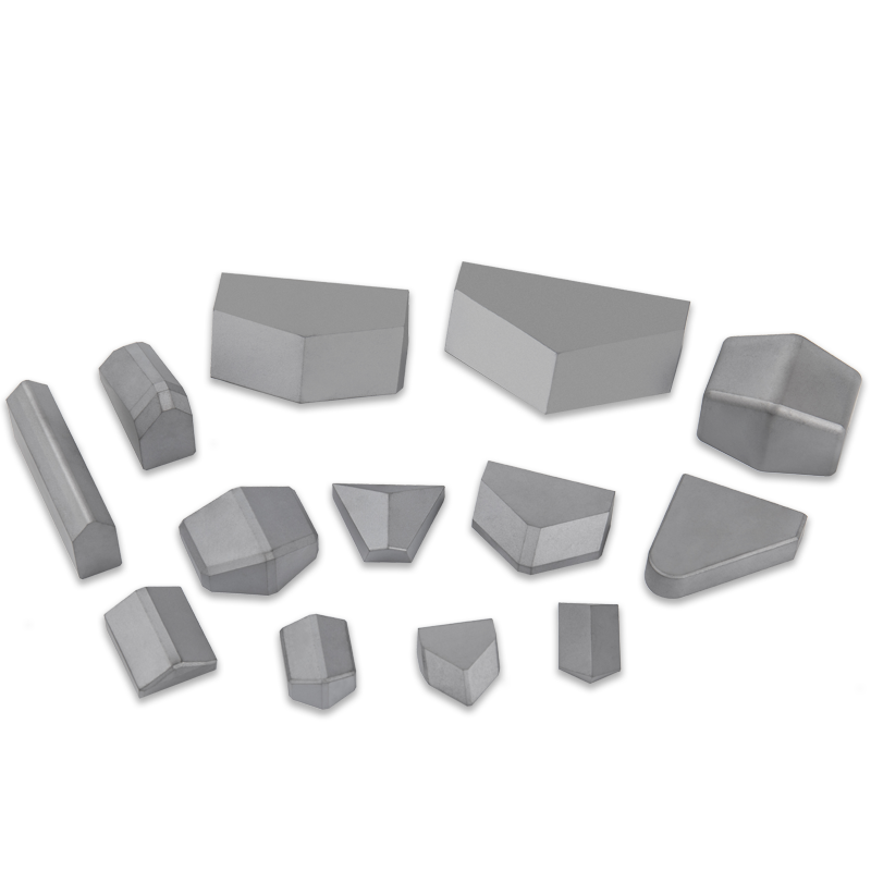
Types of TBM Carbide Inserts and Their Functions
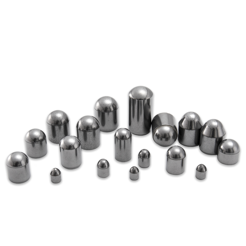
Not all tungsten carbide inserts on a TBM cutterhead perform the same function. The cutterhead is a complex assembly of different tool types, each positioned to perform a specific task in the rock breaking and material removal process. Understanding the distinctions between these insert types is fundamental to specifying the right carbide grade and geometry for each position.
Disc Cutter Inserts
Disc cutters are the primary cutting tools on hard rock TBMs. A disc cutter consists of a steel ring — the disc — mounted on a hub assembly that allows it to rotate freely as the cutterhead turns. The disc edge contacts the rock face and generates tensile fractures through a rolling indentation mechanism rather than direct cutting. Tungsten carbide inserts in disc cutter applications are typically embedded in the disc ring edge or used as the contact edge material in composite disc designs. These inserts must resist high compressive stresses at the rock contact point, fatigue loading from repeated impact cycles, and abrasive wear from hard minerals — particularly quartz — in the rock matrix. Grades with medium cobalt content (8–12% Co) and fine-to-medium grain size are commonly specified for disc cutter inserts in hard rock applications.
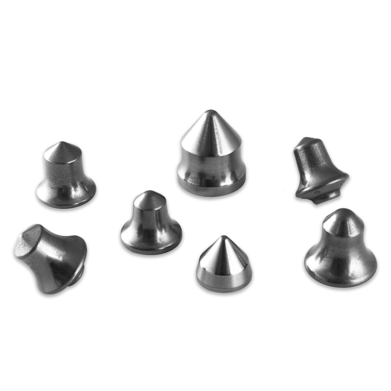
Button and Stud Inserts for Drag Tools
In soft to medium-hard ground and mixed-face conditions, TBMs use drag tools — picks, scrapers, and gauge cutters — fitted with tungsten carbide button or stud inserts that engage the formation in a scraping or shearing action. Button inserts are hemispherical or ballistic-profile carbide shapes press-fitted into the steel tool body; stud inserts are cylindrical shanks with a hardened tip, also press-fitted or brazed into prepared seats. These inserts experience lower compressive loads than disc cutter inserts but are subjected to higher lateral shear forces and more variable impact from mixed rock-soil contacts. Grades with higher cobalt content (12–16% Co) and coarser grain size provide the toughness needed to resist fracture under these loading conditions, at the cost of some abrasion resistance relative to harder low-cobalt grades.
Gauge and Gage Cutter Inserts
Gauge cutters are positioned at the outer perimeter of the TBM cutterhead and cut the tunnel profile to the required diameter. They experience a combination of the highest cutting speeds — because they travel the greatest circumferential distance per rotation — and significant impact loading from profile irregularities and mixed ground conditions at the tunnel boundary. Gauge cutter inserts are subject to some of the most severe wear conditions on the cutterhead, which is why they are often specified in tougher grades or with larger insert dimensions that provide more carbide volume to resist wear before the insert needs replacement.
Bucketwheel and Spoke Tip Inserts
On EPB (Earth Pressure Balance) and slurry TBMs operating in soft ground or mixed face conditions, the cutterhead spokes and bucketwheel openings are fitted with carbide-tipped wearing elements that protect the steel structure from abrasive wear as loosened material is scooped into the machine. These wear protection inserts are generally specified in high-toughness grades that resist impact from rock fragments and hard inclusions in the muck stream, prioritizing structural integrity over cutting edge sharpness.
Carbide Grade Selection by Rock Type and Abrasivity
The geological conditions at the tunnel face are the primary driver of carbide insert grade selection. Rock abrasivity — quantified through standardized tests such as the Cerchar Abrasivity Index (CAI) and the LCPC abrasimeter test — directly predicts the rate at which carbide inserts will wear and the likelihood of catastrophic fracture under impact loading. Matching insert grade to rock abrasivity is the most important single decision in TBM carbide insert specification.
| Rock Type | Typical CAI Range | Recommended Co Content | Grain Size | Primary Wear Mechanism |
| Limestone / Marble | 0.1–0.5 | 10–14% | Medium | Low abrasion; impact from fracture planes |
| Sandstone | 0.5–2.5 | 8–12% | Fine to medium | Moderate abrasion from quartz grains |
| Granite | 2.0–4.5 | 6–10% | Fine | High abrasion; fatigue cracking |
| Quartzite | 3.5–6.0 | 6–9% | Ultrafine to fine | Severe abrasion; micro-chipping |
| Basalt / Dolerite | 1.5–3.5 | 8–12% | Fine to medium | Abrasion and impact from hard inclusions |
| Mixed face / Glacial till | Variable | 12–16% | Medium to coarse | Impact fracture from cobbles; variable abrasion |
The CAI threshold of approximately 2.0 is a practical decision point in carbide grade selection. Below this value, higher cobalt content grades with medium grain size deliver a good balance of toughness and wear resistance. Above CAI 2.0, the abrasive wear rate of higher-cobalt grades becomes uneconomical, and the specification should shift toward lower cobalt content, finer grain grades that maintain hardness at the cost of some toughness. In formations above CAI 4.0 — extreme quartzite and some abrasive conglomerates — even premium fine-grain low-cobalt grades wear rapidly, and insert replacement frequency becomes a project planning factor rather than an avoidable cost.
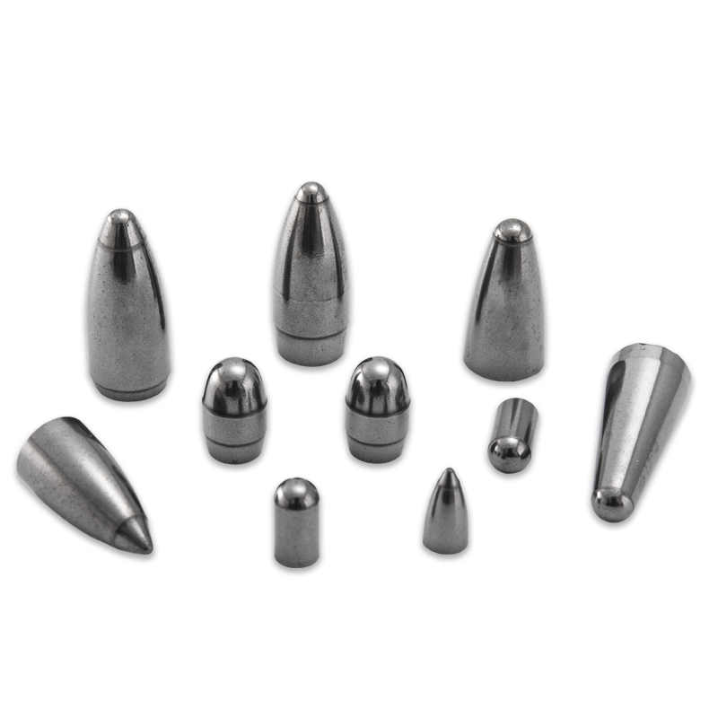
Insert Geometry and Its Effect on Cutting Performance
The geometry of a tungsten carbide TBM insert — its profile shape, tip angle, and dimensional proportions — determines how it engages the rock face, how it distributes stress within the carbide body, and how its performance evolves as the insert wears. Geometry optimization is as important as grade selection in maximizing insert life and cutting efficiency.
Hemispherical Button Inserts
The hemispherical profile is the most common geometry for drag tool button inserts in soft to medium-hard ground. The rounded tip distributes contact stress evenly over a large surface area, reducing peak stress concentrations that would cause fracture in a sharper profile. As the hemisphere wears, its geometry evolves gradually — a partially worn hemisphere is still a functional cutting profile, which means the insert continues to perform through a significant portion of its volume before replacement is needed. The main limitation of the hemispherical profile in hard rock is that it requires higher penetration forces to achieve the same indentation depth compared to sharper profiles, which reduces cutting efficiency in formations where penetration force is the limiting factor.
Ballistic and Conical Profiles
Ballistic inserts have an ogive tip profile — rounded at the point but transitioning to a more cylindrical body at a steeper angle than a hemisphere. This geometry concentrates the contact stress more effectively than a hemisphere, improving penetration in harder rock at the same applied force, but it is more susceptible to fracture if impacted laterally or used in formations with hard inclusions. Conical inserts with a defined tip angle extend the penetration efficiency advantage further but are the most fracture-prone of the standard profiles. Conical and ballistic TBM carbide inserts are typically specified for formations where cutting efficiency is the priority and impact loading is predictable and manageable.
Chisel and Wedge Profiles
Chisel-profile inserts present a linear cutting edge rather than a point contact to the rock face. This geometry is effective for shearing and scraping soft to medium formations and is commonly used in gauge cutter and profile cutter positions where a defined cut geometry is needed. The chisel edge wears to a flat quickly under abrasive conditions, transitioning the cutting mechanism from shearing to plowing — a significant performance change that increases the required cutting force and generates more heat at the insert face. Monitoring chisel insert wear and replacing at or before the flat wear threshold is therefore more time-critical than with button insert geometries.
Wear Mechanisms and How to Recognize Them
Identifying the specific wear mechanism affecting TBM carbide inserts in the field is the starting point for diagnosing whether the current insert specification is appropriate for the ground conditions and whether interventions — grade change, geometry change, operating parameter adjustment — are likely to improve performance. The main wear modes are distinct in appearance and have different root causes.
- Abrasive wear (flat wear): Progressive removal of carbide material from the insert tip surface by hard mineral grains in the rock, producing a smooth flat or faceted worn surface. This is the expected wear mode in abrasive formations and indicates that the insert is consuming carbide volume at a rate determined by the rock abrasivity and the hardness of the carbide grade. If flat wear rate is higher than expected, consider shifting to a lower cobalt, finer grain grade — but ensure toughness remains sufficient for the impact conditions present.
- Chipping and micro-fracture: Small-scale fracturing of the carbide tip, visible as irregular edge breaks or pitted surface texture. Chipping typically indicates that the current grade is too hard and brittle for the impact conditions present — the carbide is fracturing before the binder can deform and absorb the impact energy. This wear mode is common when a low-cobalt grade specified for abrasive conditions encounters unexpected hard inclusions or fracture zones. The solution is usually to increase cobalt content or grain size to improve toughness.
- Gross fracture: Catastrophic breakage of the insert body, losing a significant portion or all of the insert above the mounting shank. This failure mode indicates severe overloading — typically from impact with unexpectedly hard boulders, sudden changes in formation strength, or incorrect insert mounting that creates stress concentrations at the insert base. Gross fracture destroys the insert immediately and can damage the tool body, making it a high-cost failure mode to avoid.
- Thermal cracking: A network of surface cracks radiating from the insert tip, sometimes called "heat checking." This occurs when frictional heat at the cutting face causes rapid thermal cycling that exceeds the carbide's thermal fatigue resistance. Thermal cracking is more common in dry cutting conditions — indicating inadequate cooling water delivery to the tool face — or when penetration rate is very high, generating sustained frictional heat. Improving cooling water supply and reviewing cutting parameters are the primary responses to thermal cracking.
- Cobalt binder leaching: In acidic groundwater or chemically aggressive pore fluids, the cobalt binder in the carbide matrix can be selectively dissolved, leaving a weakened carbide skeleton that is highly susceptible to fracture. This failure mode is identifiable by a porous, gray surface texture on the insert and is confirmed by chemical analysis of the groundwater. Nickel or nickel-chromium bonded carbide grades offer significantly better corrosion resistance in acidic conditions and should be specified when binder leaching is a known or suspected risk.
Installation, Inspection, and Replacement Practices
The performance of tungsten carbide inserts in service is significantly affected by the quality of installation, the frequency and rigor of inspection during tunneling, and the criteria used to trigger replacement. Poor practice in any of these areas reduces insert service life and increases per-meter tooling costs, regardless of how well the carbide grade is specified.
Installation Requirements
Press-fit button inserts must be installed with the correct interference fit between the insert shank and the prepared seat in the tool body. Too little interference allows the insert to rotate or loosen under cutting forces, accelerating wear and eventually leading to insert loss; too much interference generates tensile hoop stress in the carbide shank at installation, which can initiate cracks that propagate to fracture in service. Manufacturers specify the required interference fit for each insert diameter and body material combination — these specifications should be followed precisely, with seat dimensions verified by gauge measurement before installation. Brazed inserts require correct brazing alloy selection, flux application, and braze joint thickness control to achieve the bond strength needed to resist cutting forces without cracking the carbide adjacent to the braze interface.
In-Service Inspection Protocols
TBM cutterhead inspection intervals vary with ground conditions and project requirements but typically occur every 300–600 meters of advance in medium-hard ground and more frequently in highly abrasive formations. During each inspection, every insert position should be visually examined for the wear modes described above, and insert wear depth should be measured at representative positions using a depth gauge. Insert wear maps — recording wear at each position on the cutterhead over successive inspection intervals — allow identification of positions with anomalously high wear rates that may indicate localized formation changes, cooling water delivery problems, or cutterhead rotation imbalance requiring investigation.
Replacement Criteria
Inserts should be replaced before they wear to the point where the steel tool body begins to contact the rock face — at that point, the tool body wears rapidly and the cost of tool body replacement far exceeds the saving from maximizing insert run time. Typical replacement criteria for button inserts specify a maximum flat wear diameter of 60–70% of the original insert diameter, beyond which wear rate accelerates nonlinearly and the risk of gross fracture increases significantly. For disc cutters, ring wear is monitored by measuring the reduction in ring diameter from the original specification, with replacement typically triggered at a wear limit of 5–10mm diameter reduction depending on the ring design.
Key Factors When Sourcing TBM Carbide Inserts
Procurement of tungsten carbide inserts for tunnel boring machines involves technical, commercial, and logistical considerations that are specific to the underground construction environment. The consequences of specifying the wrong product or running out of stock mid-drive are severe enough to make the sourcing decision significantly more consequential than for most industrial consumable purchases.
- Request material certifications and grade data sheets. Any reputable carbide insert supplier should provide material test certificates confirming hardness (HRA or HV30), transverse rupture strength, density, and cobalt content for each production batch. Verify that the supplied grade matches the specification and that batch-to-batch consistency is maintained — grade variation between batches is a known quality issue with some manufacturers operating at the commodity end of the market.
- Confirm dimensional tolerances against your tool body specifications. Insert shank diameter tolerances for press-fit applications are typically specified in the range of ±0.01–0.02mm. Request dimensional inspection reports confirming that the supplied inserts meet the specified tolerance band — out-of-tolerance inserts cannot be detected visually and will cause installation problems or premature failure in service.
- Maintain adequate safety stock for the project duration. TBM drives in abrasive ground consume inserts rapidly — consumption rates of several hundred inserts per week are not unusual in highly abrasive granite or quartzite drives. Establish a consumption forecast based on the expected formation abrasivity, planned penetration rates, and cutterhead design, and size safety stock to cover at least four to six weeks of forecast consumption at the project site. Supply chain disruptions during an active TBM drive have a direct and immediate impact on project schedule.
- Consider total cost of ownership rather than unit price. A carbide insert that costs 20% more but lasts 50% longer in a given formation reduces tooling cost per meter of advance by approximately 25% while also reducing the labor cost of inspection and replacement interventions. Evaluating insert suppliers on cost-per-meter performance data from comparable projects rather than unit price alone consistently produces better project outcomes and is the approach used by experienced TBM contractors globally.
- Engage supplier technical support for novel or challenging formations. When the project geology includes formations outside the standard hard rock or soft ground categories — highly fractured rock, chemically aggressive groundwater, extreme abrasivity, or mixed face with large boulders — work with the insert supplier's technical team to develop and validate the insert specification before the drive begins. The cost of a pre-project technical review is negligible compared to the cost of discovering an inadequate specification through premature insert failure during a live drive.
Our Products //
Related Products

If you are interested in our products, please consult us
